Extracting and reversing the firmware of the DC30 badge to beat the badge challenge!
Table of contents
Backstory and Objective
Once upon a time I was very excited to fly to Las Vegas and attend DEFCON 30 the annual go-to security conference. This was going to be my first conference and I had purchased pre-registration tickets, which was a new system that DEFCON was using to allow attendees to guarantee a badge and semi-skip LINECON. However, because of a personal emergency that appeared last minute, I was unable to attend and I gifted my pre-registration to my good friend and mentor playoff-rondo. Later on when I was catching up with him he gave me his badge. DEFCON badges usually have some sort of challenge on them and this year’s badge was some sort of piano keyboard. This is the writeup made by the attendee that solved the badge challenge and won a black badge, as you can see it is meant to be solved in part by interacting with other attendees who have a different variant of the badge. This is obviously not possible for me, so my goal was to reverse engineer the badge and find what key combo needs to be pressed in order to win the first part of the challenge.
Part 1: Extracting Firmware from SPI Flash
I began by using a magnifying glass, pen and paper to identify all the visible chips on the PCB.
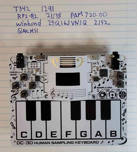
The two important chips to note are the Winbond W25Q16JV (flash chip) and the RP2 B2 (microcontroller). The flash memory chip will be used to grab the firmware and will be the target chip to physically extract. The microcontroller will be used to determine the architecture, conventions and other information that will be useful when analyzing the firmware.
There are tools available to extract firmware from a surface-mounted chip without having to actually remove the component, however I will be using a TL866II+ universal programmer, so I will have to remove the chip from the PCB, feed the chip to the device using the appropriate adapter and connect the programmer to my VM for extraction. A heat gun would be ideal for removing a small surface mounted chip like this without damaging the PCB, however I do not have access to such equipment, so I use a soldering iron and tweezers. I heat up each joint of the chip with the iron and lift the leg up with tweezers and a magnifying glass. After I have detached the chip from the board, I go around with the iron again and a desoldering pump in an attempt to clean up as much excess solder as possible from each leg. Then I lock the flash chip in the corresponding adapter and insert it into the TL866II+.

Unfortunately, the whole ordeal was pretty messy and resulted in a bit of copper from the PCB being destroyed.

In my ubuntu machine I use the minipro program to interact with the chip programmer. The following command writes the firmware to a file. ``` minipro -p "W25Q16JV@SOIC8" -r flash.bin ```
I can verify that this is the firmware by running strings and examining the output.

Part 2: Analyzing Firmware and Finding the Comparison Function
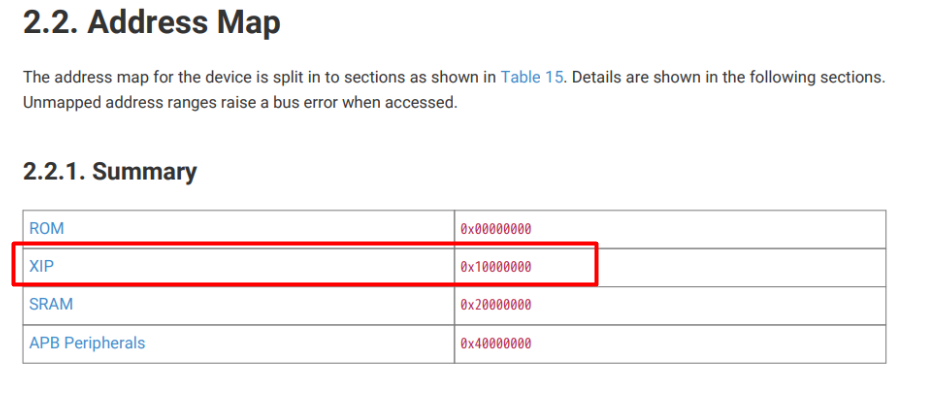
The MCU is a rpi2040 which makes use of the “execute in place” feature. This is a feature that improves performance by enabling execution directly in flash storage rather than execution in the MCU’s limited memory area. It is important that we keep this in mind before starting to analyze the firmware. Firmware has no entry point and instead has a defined address at which program execution begins. We can find this base address by viewing the rpi2040 datasheet and navigating to the “Address Map” page from the table of contents. The base address will be the XIP address (execute in place). We need to specify this address as the base address in whatever we use to analyze the firmware to load the correct segment.
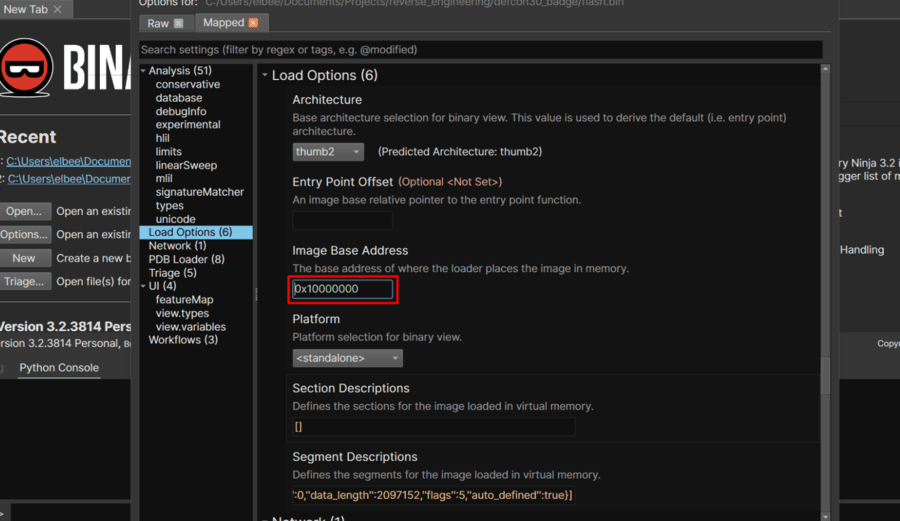
Using Binaryninja I can specify the base address when creating a new project. Binja automatically detects the thumb2 ARM architecture.
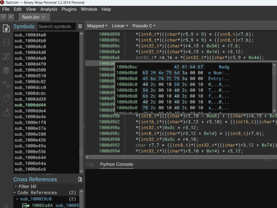
I start to try and identify useful symbols and organize the code by searching through strings and going to their code references.

Some areas have been incorrectly loaded as symbols so I undefine them.

I also rename symbols that have obvious functions for clarity.
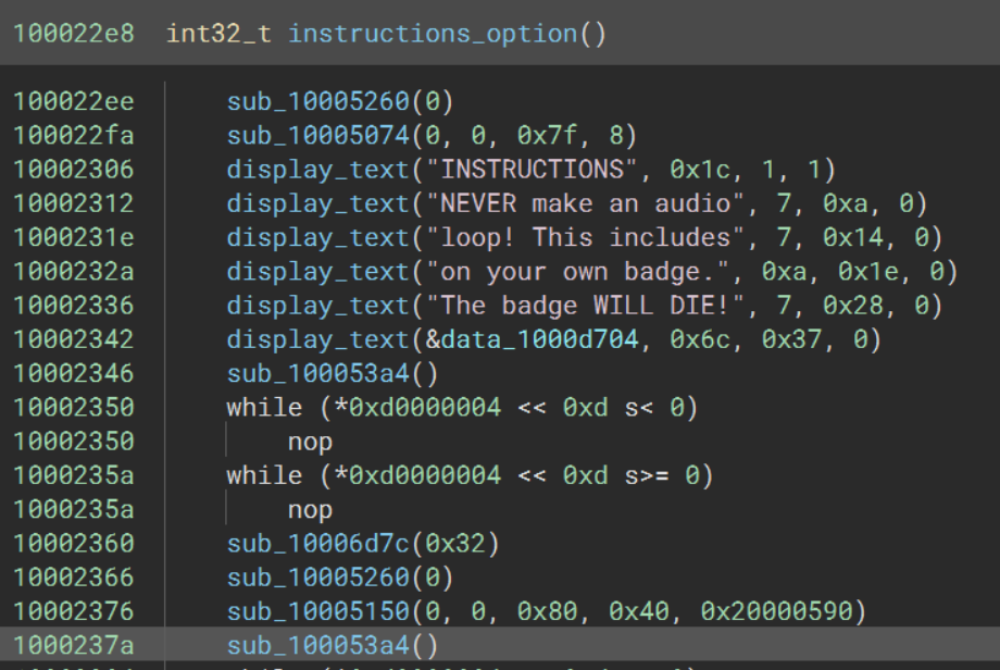
Identifying and following the code reference of the interesting string, “YOU DID IT!” leads to what seems to be the function that is called when a correct key combination is entered.
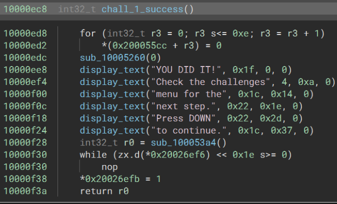
The only code reference leads to the following function. The first thing I noted when initially examining it was the comparison inside the loop to 0x2d. This conditional is equal to if(r3_1 == 0x2d(which is 46)) since the if-statement ends in a break. Examining the note count on my own badge and noting the number of badges with different variations, we know the total number of piano keys that make-up the passing combo is 46, since all badge’s music sheets will be used.

The decompilation process complicated this loop a bit, so for sanity’s sake lets simplify it a bit in our heads. The while loop iterates over the length of the correct combo, once it reaches 46 (the length of the combo) it succeeds. The second if-statement is most important, it compares every key (it gets the key by referencing the location of the key presses in memory with the offset of the current index) with the given character at string[index] if it is not equal, it breaks ending the while loop early and never reaching the success block, else it increments combo_length. So the string in the second conditional is what we need to pay attention too.
C@><>@C@><>@C@CE@EC@><C@><>@C@><>@>@C@CE@EGDB@
Since each key press is being compared with this string, it is safe to assume that each character in this string is mapped to a physical key on the badge. We should find another function which identifies this mapping. This would likely be the keypress code blobs directly.
Some things to note before continuing:
- User key buffer stored @ 0x2000xxxx (keypresses).
- The checkwin function will likely be called every time a key is pressed, to check if the newly modified buffer is a win.
Part 3: Finding the Mapping and Decoding the Key Combo
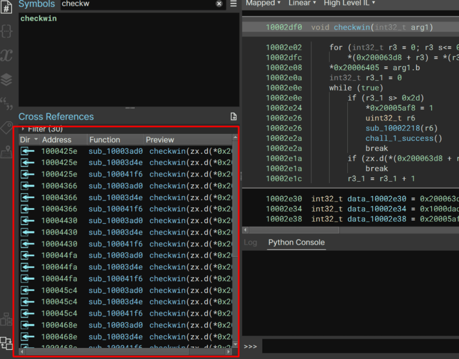
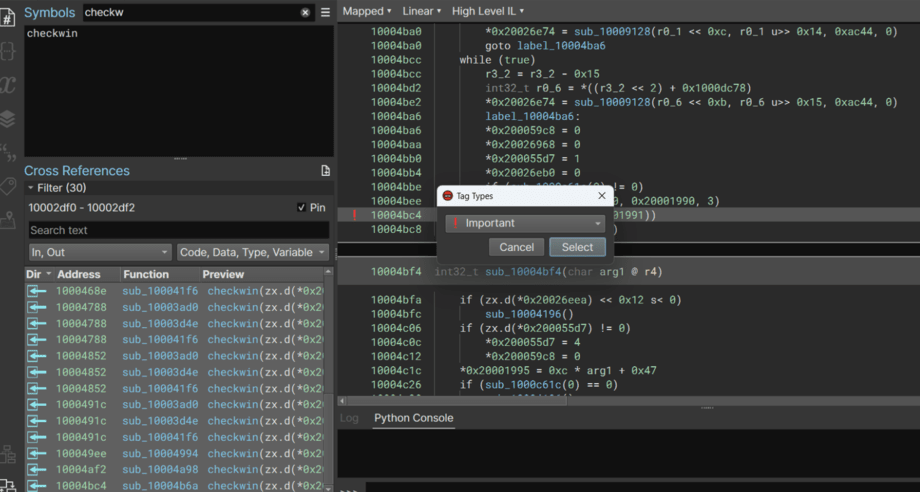
checkwin has a lot of code references. Each call is likely in a blob for a key press. I’ll pin the references window and tag them all to keep everything organized and visible on the pane.
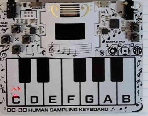
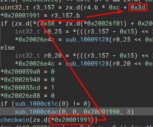
Examining the very first reference we can take note that a pointer is being passed as the argument. The value at this pointer is being assigned above. For this instance that value is 0x3c, whose ascii representation is “<”.

Each blob that assigns a mapping is sequential in the code block, so I can safely assume that these are the keyboard mappings assigned in the order as they appear on the physical keyboard.
Proceeding to the next checkwin call will reveal the mapping for the C# key (the little black key) which comes next.
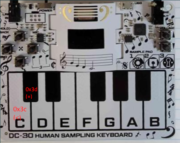
Proceeding through every checkwin call will reveal the character mappings for the entire keyboard.
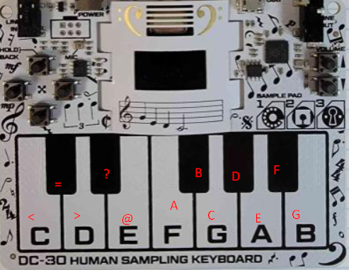
Hurray!
With these mappings we can decipher the string compared in the checkwin function to the equivalent keys on the keyboard.
key_map = {"<":"C","=":"C#",">":"D","?":"D#","@":"E","A":"F",
"B":"F#","C":"G","D":"G#","E":"A","F":"A#","G":"B"}
key_combo = ""
for c in "C@><>@C@><>@C@CE@EC@><C@><>@C@><>@>@C@CE@EGDB@":
  key_combo += key_map.get(c)+" "

print(key_combo)
The following is the correct key-combination/tune we need to play on the badge keyboard in order to pass the first challenge.
G E D C D E G E D C D E G E G A E A G E D C G E D C D E G E D C D E D E G E G A E A B G# F# E